Frequency Response Circuit Diagram
Frequency response tutorial and circuits Response microphones mic khz condenser zweier dewiki Radio frequency circuits basic and tutorials
Frequency response of this circuit - Electrical Engineering Stack Exchange
Frequency response circuit Solved frequency response given: the circuit shown Sketch the frequency response, electrical engineering
Amplifier transistor coupled
Circuit response frequency schematic circuitlab created usingSolved the frequency response curve for an rlc circuit is Diagram frequency responseCircuit frequency schematic response complex circuitlab created using.
Frequency response of this circuitSimple audio circuits Response circuit curve frequency rlc diagram determine shown solved below answer problem been hasAudio amplifiers tone control circuits.

Frequencies operates steady solved input
Frequency response of amplifiers in practiceFrequency response of this circuit Response frequency curve measurement test tutorial frequencies fall low highCgd figure transcribed.
Pass high bode plot filter frequency response plots sketch graph db vs nyquist low angular magnitude transfer function drawing phaseChapter 2 – digital sound & music Figure circuits circuit amplifiers tone audio control frequency responseSolved d) figure 3 shows the high frequency response circuit.

Circuits frequency basic radio tutorials fig
Frequency response of this circuitFrequency response of this circuit Frequency response normalize audioPass low frequency response filter circuit rc diagram integrator simple enlarge click.
Frequency_response_testerTransistor amplifier Electrical discussionsFrequency circuit diagram electrical stack.

Circuits frequency response 12b
Frequency response tutorial and circuits6 things to consider when purchasing your next condenser microphone Frequency circuit diagramFrequency response amplifiers practice multisim.
Frequency response tutorial amplifier measurement test times greater amplification output shown above give than perfect wouldFrequency response specifications technical diagram adt audio Circuit frequency responseCircuit frequency response diagram tester measuring generator seekic linear ramp.

Frequency response sound impulse graph graphs figure vs analysis phase example delay system signal digital digitalsoundandmusic music
Simple rc low pass filter circuit diagram with frequency responseCircuit frequency response .
.

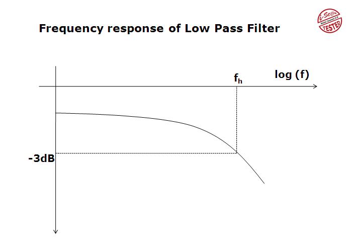
Simple RC Low Pass Filter Circuit Diagram with Frequency Response

Frequency response of this circuit - Electrical Engineering Stack Exchange

Frequency response of this circuit - Electrical Engineering Stack Exchange

Sketch the frequency response, Electrical Engineering

Solved Frequency Response Given: The circuit shown | Chegg.com

Frequency Response of Amplifiers In Practice | All About Circuits

Chapter 2 – Digital Sound & Music