Earth Tester Circuit Diagram
Tester connections Earth testers Circuit elcb simple homemade leakage earth circuits breaker electronic diagram hobby projects electronics phase diy
LIVE, Neutral, Earth Fault Indicator Circuit | Homemade Circuit Projects
Schematic diagram of earth tester. Tester socket mains circuit detect indication 240v earthing live 230v wiring power neutral testers switched do terminal detection marc electrical Earth testers
Resistance earthing earth tester measurement measure test electrical detail perform measuring technique explain right will
Live, neutral, earth fault indicator circuitEarth circuit neutral fault indicator live phase ac circuits leakage led homemade show pcb wrong indications using Hioki tester grounding testersEarthing resistance tester.
Resistance ground earth grounding voltage tester values testers hioki detectors phase installations reference typesTester earth grounding triangular Engineering photos,videos and articels (engineering search engineApplications shown types construction.

Tester resistance
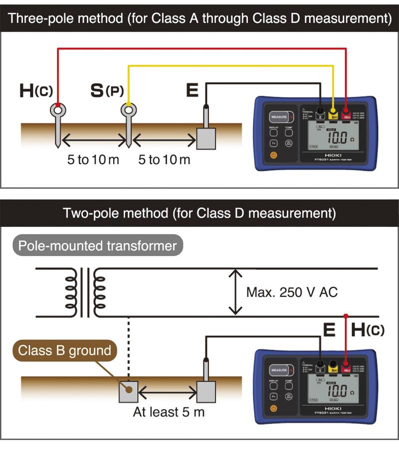
Earth tester ft6031-03Schematic diagram of earth tester. Yokogawa multimeterResistance ground grounding class pole tester hioki earth measuring cubicle method installation testers.
Earth tester resistance circuit construction measurement megger works dc ac rectifier current type medium circuitglobeEarth testers Earth earthing tester resistance ground procedureGround resistance testers tester hioki detectors voltage phase measurements example using.

Earth testers
From the q and aVoltage ground detectors resistance detector principle testers phase hioki 2 simple earth leakage circuit breaker (elcb) explainedEarth point test ground three tester voltage soil current nutsvolts.
Earth testerEarth resistance tester principle working test measure arduino current fig voltage electrodes means transformer loop topic electrical board ammeter voltmeter Earth tester : procedure to measure earth resistance and its applicationsEarth tester or earth resistance tester.

What is earth tester?
Electrical topics: working principle of earth resistance testerCapacitor circuit tester diagram flasher cum electronic working projects Tester ground circuit safety simple diagramCircuit diagram of capacitor tester.
Earth tester : procedure to measure earth resistance and its applicationsHow to check earth resistance using multimeter Simple ground tester safety circuit diagram.


grounding - Earthing terminal detection and indication - Electrical

Earth Testers | Ground Resistance Testers | Voltage Detectors | Phase

Earth Testers | Ground Resistance Testers | Voltage Detectors | Phase

electrical topics: Working Principle of Earth Resistance Tester
EARTH TESTER FT6031-03 | Hioki

What is Earth Tester? - Definition & Construction - Circuit Globe

LIVE, Neutral, Earth Fault Indicator Circuit | Homemade Circuit Projects

Earth Testers | Ground Resistance Testers | Voltage Detectors | Phase